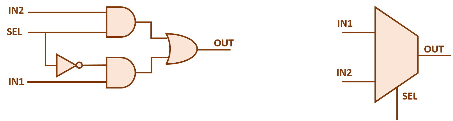
4 x 1 mux using logic gates Mux circuit logic gates using circuitlab input electronics make once working questions need two Make an or gate using a mux
Multiplexer (Mux) - Types, Cascading, Multiplexing Techniques, Application
Mux multiplexer 8x1 diagram logic table schematic truth using input vlsi 2x1 symbol muxes structure elcho figure eda
Multiplexer (mux)
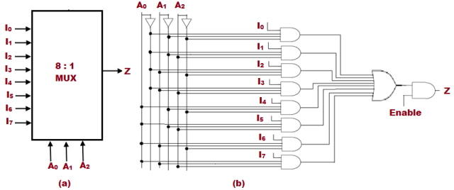
Mux multiplexer cascading multiplexing logic bits8x1 mux logic diagram : using 8 1 multiplexers to implement logical Multiplexer mux applications demultiplexer diagram logic circuit types multiplexers chess board demux explain electronic making january use lowA multiplexer schematic structure, b truth table of the mux based on.
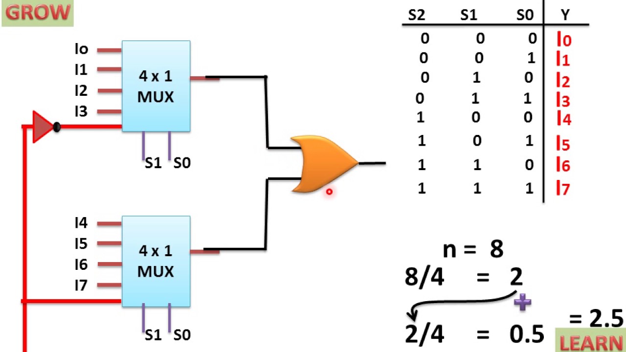
8 to 1 multiplexer logic diagram and truth tableMux multiplexer cascading multiplexing techniques Mux using gate 2to1 make figure copyMultiplexer (mux).
![Multiplexer (Mux) - Types, Cascading, Multiplexing Techniques, Application](https://i2.wp.com/electricalfundablog.com/wp-content/uploads/2019/12/mux-4_thumb.png)
8x1 mux multiplexer 4x1 logic implementation implement multiplexers logical 2x1
Mux multiplexer cascading multiplexing techniques bitsImplement and gate using 2:1 mux 8 to 1 muxMux 8x1 transmission gate multiplexer logic cheggcdn.
8x1 mux logic diagram / 8x1 mux logic diagram2x1 mux : vlsi n eda 2x1 mux multiplexer diagram logic schematic symbol vlsi using gates inverter input eda figureMux multiplexer vhdl using logic gates code use.
![8 To 1 Mux](https://i2.wp.com/www.tankbig.com/wp-content/uploads/2019/01/63_4.jpg)
Multiplexer mux nand inputs multiplexing boolean expression dip fortunately elcho
Vhdl 4 to 1 mux (multiplexer)Multiplexer (mux) Mux gate using implement.
.
![VHDL 4 to 1 MUX (Multiplexer)](https://i2.wp.com/allaboutfpga.com/wp-content/uploads/2016/01/MUX-4-TO-1-USING-LOGIC-GATES.png)
![Make an OR gate using a MUX | VLSI Design Interview Questions With](https://i2.wp.com/vlsiinterviewquestions.org/wp-content/uploads/2012/04/or_using_2to1_mux-Copy-Copy.jpg)
![8X1 Mux Logic Diagram / 8x1 Mux Logic Diagram - Wiring Diagram Schemas](https://i2.wp.com/media.cheggcdn.com/media/d33/s811x645/d330f27b-330b-4244-9d74-4f5a7eab5b47/phpzSnO5b.png)
![Multiplexer (Mux) - Types, Cascading, Multiplexing Techniques, Application](https://i2.wp.com/electricalfundablog.com/wp-content/uploads/2019/12/2-is-to-1-Mux-3.png)
![8X1 Mux Logic Diagram : Using 8 1 Multiplexers To Implement Logical](https://i.ytimg.com/vi/iUtJQveRKjQ/maxresdefault.jpg)
![Implement AND gate using 2:1 MUX | design AND gate using MUX/ create](https://i.ytimg.com/vi/IXDJF0Gj6hY/maxresdefault.jpg)
![2x1 mux : VLSI n EDA](https://4.bp.blogspot.com/-8Psaaa01UAE/V2tJ_UWpDlI/AAAAAAAAAZM/MxxMEpyTiyMvop1XzgIXyENeFQNrOvpHwCK4B/s1600/2x1%2Bmux%2Bdiagram.png)
![Multiplexer (Mux) - Types, Cascading, Multiplexing Techniques, Application](https://i2.wp.com/electricalfundablog.com/wp-content/uploads/2019/12/8-to-1_thumb.png)
![a Multiplexer schematic structure, b truth table of the mux based on](https://i2.wp.com/www.researchgate.net/publication/340612297/figure/fig14/AS:962178924441600@1606412740008/a-Multiplexer-schematic-structure-b-truth-table-of-the-mux-based-on-inputs-c-truth.png)
![Modern Circuit Design — COSC2325 fall2018 documentation](https://i2.wp.com/www.co-pylit.org/courses/cosc2325/_images/4-to-1-mux.png)